Saturday 28 April 2007

Ever decreasing circles

I wrote some test code in Python to check that my firmware was working properly. This turned out to be incredibly easy using the socket and struct modules. I have not written a lot of Python before but it never ceases to amaze me how much more productive it is compared to C++. Handling the Ethernet UDP comms required only a few lines of code. Here are extracts from the constructor and destructor :-
from socket import *
from struct import *

class Hydra:
def __init__(self, ip_addr):
# Create sockets
self.sendSock = socket(AF_INET,SOCK_DGRAM)
self.sendAddr = (ip_addr,21000)

self.recvSock = socket(AF_INET,SOCK_DGRAM)
self.recvSock.bind(("",21001))
self.recvSock.settimeout(0.1)

def __del__(self):
# Close sockets
self.recvSock.close()
self.sendSock.close()
Below is the code that sends a command and receives the reply. UDP packets are not guaranteed to arrive at their destination and if they do they are not guaranteed to arrive in the same order they were sent in, although on a small single segment LAN they generally do. Packets are protected by CRCs and checksums so if you do receive a packet you can be pretty sure it is not corrupt.

To make a reliable protocol timeouts, retries and packet sequence numbers are required. I also added a 4 byte magic number at the start of each packet just to make sure a stray packet from a rogue application or the Web could not cause HydraRaptor to lose the plot.
    def do_cmd(self,cmd):
tries = 3
while tries:
self.sendSock.sendto('\x12\x34\x56\x78' + cmd,self.sendAddr)
try:
data,addr = self.recvSock.recvfrom(1024)
return data
except timeout:
print "read failed"
tries = tries - 1
raise 'comms failed'
Here is the code to wait for the machine to be ready and then instruct it to go to to a 3D position.
   def get_status(self):
return unpack('>hhhhBB', self.do_cmd('\x00\x00'))

def goto_xyz(self,pos,delay):
while 1:
a, b, c, steps, seq, ready = self.get_status()
if steps == 0 and ready:
break
seq = (seq + 1) & 255
self.do_cmd(pack('>BBhhhh', self.goto_xyz_cmd, seq, pos[0], pos[1], pos[2], delay))
Notice how easy it is to marshal and unmarshal packets using the struct module. The big endian to little endian conversion is handled simply by putting a > sign at the start of the format string.

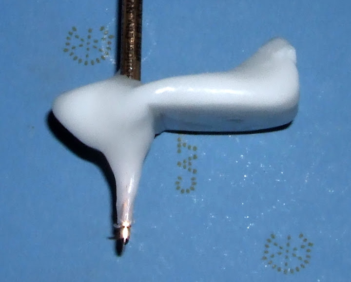
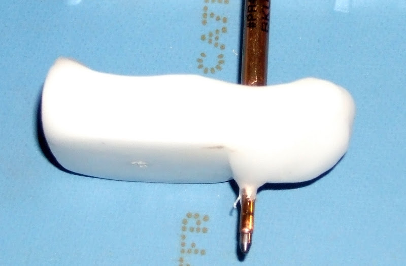
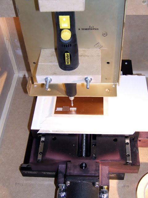
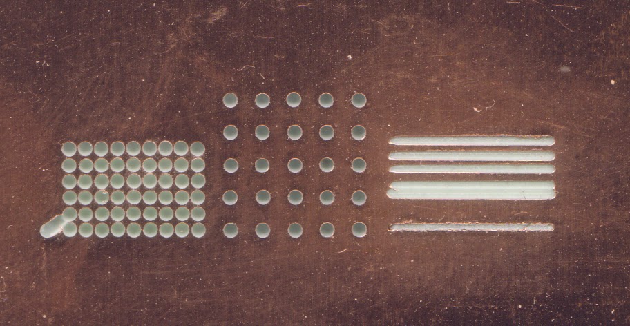
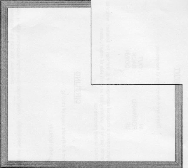
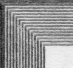
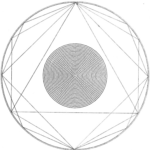
Below are some test patterns. The 25 circles in the centre are 1 - 25mm radius and are drawn with the minimum number of line segments to keep within 0.05mm accuracy. This is calculated with the formula
π / acos((r - 0.05) / (r + 0.05))
The outer circle is made with 360 line segments.


Not only can I now drive HydraRaptor from a script but I can also interact directly with it via the command line:
>>> hydra = Hydra("10.0.0.42")
>>> print hydra
At (9944,11943,400) steps = 0
>>> hydra.goto_xyz((0,0,0),1000)
>>> print hydra
At (3310,3976,133) steps = 3976
>>> print hydra
At (0,0,0) steps = 0
>>>
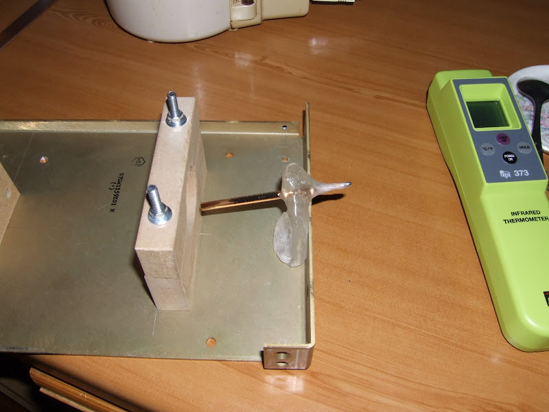
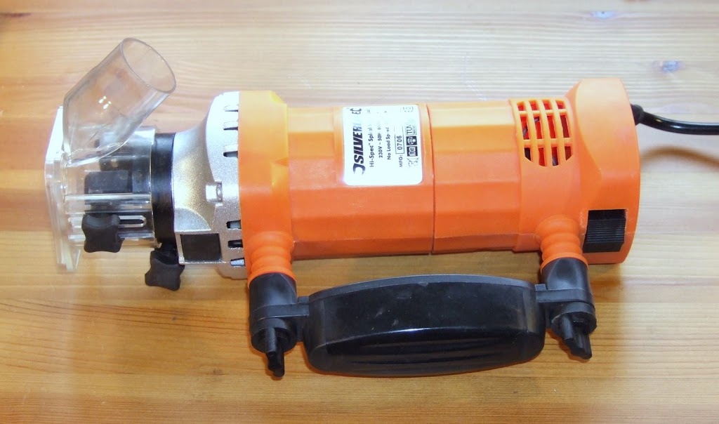
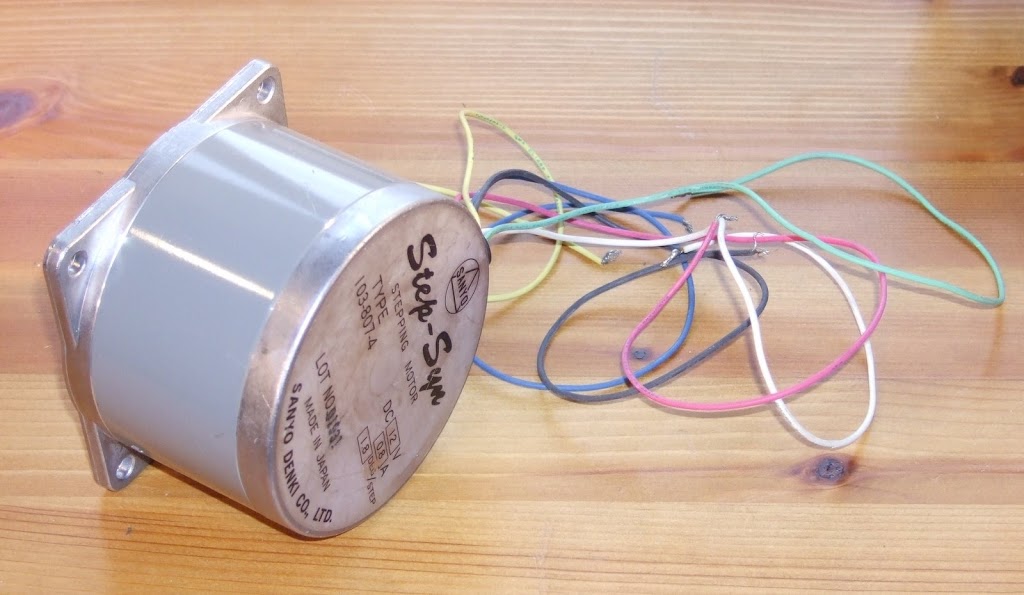
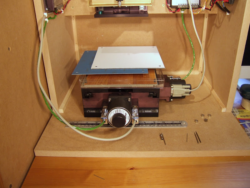
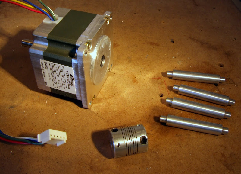
I noticed that although the Z axis is repeatable in the short term the distance to the paper varied by about 0.1mm over a two day period. I expect this is due to the MDF expanding and contracting slightly. I plan to make a tool height sensor mounted on the XY table to make it easy to switch tools. This should also compensate for the wood changes.

The next thing to do is use my existing milling setup to make some motor mounts to make an improved milling machine. To do this I will extend my Python script to allow me to define an outline as a list of lines and arcs and then mill around it.

I will then try to make the RepRap FDM extruder with the improved milling machine.

Wednesday 25 April 2007

Microwaving PolyMorph

Following a discussion in the RepRap forums I decided to find out what happens if you microwave PolyMorph. I placed about 25g in a glass dish together with a mug of water in our 650W microwave oven.


I tried 30 seconds of defrost first which had very little effect. Next I tried 30 seconds of full power. That raised the temperature of the water to 40°C but had little effect on the PolyMorph. A further minute got the water to 60°C and the PolyMorph to 30°C. After another minute the water boiled and the PolyMorph got to 41°C. I replaced the water with cold and heated it for another 2 minutes. At that point the PolyMorph was at 80°C and most of it had melted.


I formed it into a ball and made a new pen holder. At the point where I took this photograph it was still too molten to support the pen.


It took quite a long time to set, longer than my first attempt using hot water. As I kept it pressed against the metal while it was setting it ended up a lot flatter. The result was not pretty because some of the unmelted granules are visible. Also the pen is welded in, whereas it was removable from the other one.


I must admit it looks almost as curved as the first one.


After drilling and bolting the holder to the metal plate the pen is held rigidly again but the holder has shrunk so that the back is about 1mm away from the back of the plate. It is the front edge which locks it in position.

Conclusions: Well I wouldn't recommend microwaving as a way of melting PolyMorph because it is not even enough. The outer edge, where it is in contact with the glass dish, is a lot cooler. Also it does not absorb microwaves anything like as well as water does.

I think most of the shrinking and curling occurs when it first cools down but I can't explain why the first one can no longer be locked in place. Maybe there is some further shrinkage over the long term.

Tuesday 24 April 2007

My PolyMorph has morphed!

I now have HydraRaptor controlled by a Python script running on my PC. I decided to test its circle drawing ability in preparation for using it to mill a large hole in the block of material shown in the last post. When I came to refit the pen holder that I made a few weeks ago I noticed it was no longer a good fit. On closer examination it appears to have curled up a bit.


A bit disappointing because I don't like making things twice. Also it doesn't bode well for objects made by FDM, although this was cast rather than extruded.

Monday 23 April 2007

Double chicken and egg

My spiral saw arrived at the weekend. Although it was dispatched the day after I ordered it, it took another 17 days to get here from Yorkshire. For some reason Business Post could not find the address. Have they never heard of Google maps ?!


Although it was only cheap it does seem to have pretty solid bearings so looks promising for routing. At 600W and revving at 30000 RPM it should rip through most things. I just hope my z-axis motor is strong enough to lift it at 1.6Kg. If it can't then I may have to counter-balance it with a weight and a pulley or else use a bigger motor like this one for example.


I don't have any torque data for it but, at 85mm diameter, it looks beefy.

I plan to make the extruder body by milling this material.


I don't know what it is but it seems very hard and rigid. My best guess is that it is some sort of epoxy type resin with possibly a metallic filler - it has a bit of a sparkle to it. I might be completely wrong though. Anybody know what it is?

The chicken and egg problem is that to make the extruder I need to use the router, but to make the router mountings I could do with using the extruder!

It speaks, but my PC has its fingers in its ears

I almost got UDP working this evening. I wrote a simple Python test script to send a "get status" command to HydraRaptor. Here it is :-
   from socket import *

# Set the socket parameters
hydra = "10.0.0.42"
inPort = 21000
inAddr = (hydra,inPort)
outPort = 21001
outAddr = ("localhost",outPort)
buf = 1024

# Create sockets
sendSock = socket(AF_INET,SOCK_DGRAM)
recvSock = socket(AF_INET,SOCK_DGRAM)
recvSock.bind(outAddr)
recvSock.settimeout(2.0)

# Send a get status command
cmd = "\x12\x34\x56\x78\x00"
if(sendSock.sendto(cmd,inAddr)):
print "Sending message ....."

# Receive the reply
try:
data,addr = recvSock.recvfrom(buf)
if data:
print " Received message '", data, "'"
except:
print "Read failed"

# Close sockets
recvSock.close()
sendSock.close()
HydraRaptor replies with its x,y,z coordinates and the number of steps remaining. The reply packet arrives at my PC which then sends an ICMP destination unreachable (port unreachable) message back. I have no idea why. netstat -ad shows :
  UDP    shuttle:21001          *:*                                    2412
[Pythonwin.exe]
Which looks to me to show that the port is being listened to. I have tried turning my firewall off but that made no difference. I am sure the problem is at the PC end because Ethereal shows me that the packets are well formed. I have had enough for this evening. Any Python socket experts out there? I have never done sockets in Python before.

It speaks!

HydraRaptor just replied to ping, so that's PHY, MAC, ARP, IP and ICMP working.

Pinging 10.0.0.42 with 32 bytes of data:

Reply from 10.0.0.42: bytes=32 time=1ms TTL=128
Reply from 10.0.0.42: bytes=32 time<1ms TTL=128

Ping statistics for 10.0.0.42:
Packets: Sent = 4, Received = 4, Lost = 0 (0% loss),
Approximate round trip times in milli-seconds:
Minimum = 0ms, Maximum = 1ms, Average = 0ms

UDP next.

Sunday 22 April 2007

Too thick

I decided to order the parts to make the extruder so that they could arrive while I was writing the firmware. The official RepRap design I am working to is here. Forrest Higgs has a simpler design here but as I have a lathe and I don't have a blowtorch I decided to stick with Adrian Bower's original for my first attempt.

I got a lot of the mechanical parts from Farnell and was most impressed with their free next day delivery.


Some of the part numbers had gone obsolete, mainly due to ROHS, so I made the following substitutions :-

Description

Original

Substitute

Steel M5 Studding517343517409
Steel M3 Nuts7587968861250
Steel M3 Washers1496878861447
Steel 25mm M3 cap screws 1001658838887

10mm PTFE rod was out of stock but I found a cheap source of 12mm rod on eBay at Fantastic Plastic.

I also ordered a 5Kg reel of HDPE filament to get started with. It cost £85 including shipping. I plan to recycle milk bottles eventually but that will require a grinder. A four pint milk bottle weighs about 25g which makes them worth about 42p each. They must cost a lot less than that to make so the implication is that this stuff, sold as plastic welding rod, is overpriced.


The reel is a bit big and heavy to mount on the machine so I will probably have to re-spool it somehow.

It is a good job that I bought the filament before I made the extruder. The instructions specify to drill out the barrel to 3mm but my filament measures 3.2mm! I have ordered a 3.3mm drill from www.toolfastdirect.co.uk.

I also bought some nichrome wire to make the heater and some J-B Weld to attach it to the barrel and provide the electrical insulation and thermal coupling.


This stuff is rated up to 600°F. It is a departure from the original design which uses PTFE tape so it will be a bit experimental. I am hoping the thermal coupling will be good enough to allow me to use the resistance of the nichrome wire to measure the temperature rather than having a separate thermistor.

A lot quicker

Here is somebody that works a lot quicker than me: reprap-wasnt-built-in-day.html !

Saturday 21 April 2007

Slow going

Not much to report as I have had little time to spend on HydraRaptor this week, should get more done this weekend though.

On the firmware front I got as far as writing the Ethernet PHY driver. This is the part of the Ethernet controller concerned with actually sending the signals down the wire. Back in the days of 10MB Ethernet this was a relatively simple line driver. With 100MB it is a lot more complicated and generally involves a DSP to compensate for signal distortion in the cable. Quite often these are separate chips but the MC9S12NE64 has one built in.

Despite the internal complexity, the interface to a PHY is straightforward. The driver just has to configure it and then wait for it to report that the link is up. One slight wrinkle I came across is that there is a bug in the silicon that drives the activity LED. Apparently the pulse it generates is too short to be seen. You can either stretch it in hardware or disable the hardware control of the LEDs and do it yourself in software, using the pins as general purpose I/O.

The next thing to do is write the MAC driver. This part of the chip is responsible for sending and receiving Ethernet packets.

Saturday 14 April 2007

Stacking up

You may notice my blog entries slow down a bit as I have now finished catching up so it has become real time. Hopefully I should get less complaints about mixing tenses in a paragraph!

I have made a clamping system to fasten PCB material to my XY table. The test using masking tape worked surprisingly well but I need to be able to turn the board over whilst maintaining alignment for double sided PCBs.


The bottom layer you can see in the picture is a plastic tray to catch the dust from milling. It is the bottom half of a Ferrero Roche chocolate box. They make great boxes but unfortunately my wife does not rate the chocolates much.

The next layer is a sacrificial piece of laminate flooring to support the PCB and prevent breakout when it is being drilled. It seems a shame to cut it up and use it this way but at £6 per square meter this piece only cost £0.17 and I can use both sides at least once.

The blue sheet is single sided PCB material. I will use the machine to route a square aperture in the middle of this at the limits of the XY table's travel. The PCB being made will rest against one corner of the aperture to locate it. Being double sided it will stand proud by 0.3mm due to the extra layer of copper.

The top layer is a 3 mm aluminium and plastic laminate that I will use to clamp the board down on two edges. I will use the machine to route a slightly smaller aperture in it than the layer below so that it overlaps slightly. The other two edges of the board will be held down with masking tape.

The whole lot is clamped by four 2 BA nuts on threaded rods that fit holes in the XY table. My XY table is imperial and the rest of the machine metric!

I am currently working on the firmware. I have replaced the test code I cobbled together just to try things out with an interrupt driven 3D Bresenham line drawing routine. Although I probably will never need to step Z at the same time as X and Y it was easier to code the general case. It makes some interesting sounds when in runs because the motors play a three note chord depending on the gradient of the line.

The code is written in C in an object oriented style even though C is not an OO langauge. I always tend to code like that and have done so since before I knew what OO was. The three axes are represented by structs that store the position, etc, along with function pointers for stepping and reading limits which is axis dependent. That way I can reuse the same Bresenham and homing code for all three axis.
typedef struct axis {
sword pos; // Current position
sword min; // Limits
sword max;
sword steps; // Number of steps to do this line
sword dir; // Direction of each step +/-1
sword acc; // Brezenham accumulator
void (*set_dir)(bool); // Virtual function to set direction output (X,Y only)
void (*start_step)(void); // Leading edge of step pulse
void (*end_step)(void); // Trailing edge of step pulse
bool (*mlimit)(void); // Read the negative limit
} axis_ty;
The next task is to link HydraRaptor to my PC using Ethernet. The demo box comes with a free TCP/IP stack but it is not very efficiently written so I will replace it with my own minimalist version. I will just implement ARP, IP, UDP and ICMP ping. I have done this before so it should not take me too long.

Wednesday 11 April 2007

The powers that be

When trying to make parts of my machine stiffer I got to wondering about the relationship between a material's thickness and its resistance to bending. It is obviously not a linear relationship because as a sheet gets thicker not only is there more material to resist bending, but the outer layers have more leverage than the inner, so it must be at least a square law. I tried googling this for some time but failed to find a formula. I did find a comment on CNCzone by somebody that thought he recollected it being a fourth power law. I can believe this because we recently had two versions of a metal box made at work, one in 0.5 mm steel and the other 0.8 mm. While the thin one was quite flimsy the 60% thicker one was very solid. Any mechanical engineers out there?

I came across another fourth power law recently on the website of the company that made my XY table. If you have a servo system moving something from A to B as fast as it can go, then going twice as fast requires 16 times the power. Some video lectures, and a lot of other useful info about servo systems, are here www.neat.com/products/corner/default.asp.

The highest power law I have ever come across is that incandescent bulb lifetime is inversely proportional to the 12th power of voltage, see www.allegromicro.com/en/Products/Design/an/an295012.pdf. Can anybody beat that?

Tuesday 10 April 2007

Trouble at' mill

Having established that the axes were all working well I decided to do some tests to check the feasibility of milling PCBs. I originally planned to use a Dremel but its shape looked difficult to mount. I saw a cheap alternative that was cylindrical so I decided to give it a try.

I made some mounts out of MDF and these were bolted onto a 2 mm aluminium plate which had some folds in it for strengthening. I could not find a source of countersunk bolts long enough to go through the top mount. Instead I used some shorter ones and made captive nuts out of PolyMorph. I did this by first drilling clearance holes from the back of the mount to a depth just longer than the bolts. I then drilled 5 mm holes through the thickness of the MDF to meet them. I filled these with molten PolyMorph. When it had set I drilled it for tapping but I found I could just screw the bolts in and they cut their own thread. This technique seems to make a successful fastener system.


I asked a friend who works for a company that owns a professional PCB mill what they place under the PCB while it is being drilled. He was kind enough to send me a sample. It is 2 mm hardboard laminated with a thin layer of hard, melamine like, substance on each side. I have not found a source for this yet but my wife, ever keen to see "junk" turned into something useful, suggested I used some laminate flooring offcuts we have in the garage. I will give this a try, but for my initial test I used the hardboard sample. I just taped it to the top of my XY table with masking tape and taped a piece of PCB material on top. The arrangement is shown below :-


And here is a magnified view of the results :-


The diagonal on the far left is where I broke a drill due to a typo in the code: step_x instead of step_z. The drill made a valiant attempt at being a milling bit before it snapped. Not a good start, this could get expensive!

The holes on the left are 1 mm on a 50 thou grid. So far I have tried to keep all the units in this blog metric but PCB measurements are traditionally done in 1000 ths of an inch because most component leads are on a 0.1" grid. Again this was a bug but it turned out to be a good test to show drill run out. The gaps between the holes should be 0.27 mm or about 10 thou.

The holes in the middle are on a 0.1" grid which was my original intention. The holes don't actually go all the way through due to end play in the drill.

The bottom slot on the right was done with the conical tool shown in the picture below :-


This has quite a fine tip but an abrasive surface rather than cutting flutes. I estimate the channel is about 20 thou but the edges are a bit ragged, particularly the top edge. The tool rotation was clockwise and the travel left to right. This means the bottom edge was climb or down milled and the top edge conventional or up milled. Climb milling is recommended for a better finish so I need to organise my tool paths to go clockwise around the outside of tracks.

The three tracks were produced with a rose burr tool like the one on the far right but smaller. The remains of it are shown in the middle. I snapped it after the test with another accident. This tool created a smoother cut. Again, the bottom edge is cleaner. The bottom track is about 20 thou, the middle one 10 thou and the top one 15 thou. The gap between tracks is about 30 thou.

My target for through hole PCBs is 10 thou tracks and 15 thou gaps. This allows one to get a track between two 60 thou pads 0.1" apart, i.e. between the legs of a chip.

Things I learned from this experiment :-

  • Not surprisingly, the cheap (£20) drill was not up to the job. It has about 1 mm end play and noticeable lateral play. It is also very noisy when mounted on the machine. I have ordered a 30000 RPM 600W laminate trimmer for £26.49. Again, I will not know the quality of the bearings until it arrives, could be another mistake.


    If that does not work I might try a Dremel or perhaps one of these :-


    This is an 800W router spindle motor for about £80.

    There is a good article on how to make your own PCB router spindle here but I think my lathe is too small.


  • The 2mm aluminium plate is not stiff enough, I got a 6mm slab from eBay to replace it.


  • The milling bit, before I broke it, was too big. I got an eight piece "carbide circuit board maker" kit from Drill Bit City for $23. They were very helpful and efficient. Again the good stuff is on the wrong side of the pond so the shipping was another $12.


    They also sell carbide end mills down to 5 thou. These are quite pricey and delicate but I might try some when the software is stable. I will need smaller clearances for fine pitch surface mount.

  • I need dust extraction and it needs to be a fairly strong suction to lift the copper chips. I can buy a 1300W vacuum cleaner from ASDA for about £17.

Despite the deficiencies noted above I think the test was reasonably successful. In fact the current set up could probably produce a working PCB. I will get the software written and debugged before I fit the new parts. A 600W router could do a lot of damage! It would bring a whole new meaning to the phrase "software crash".

Monday 9 April 2007

Pen pusher

As others have done before me, I decided to test the Cartesian system by turning it into an over engineered pen plotter. I used the refill out of a Fisher Space Pen which apparently "is the most advanced writing instrument in the world". If so, when controlled to a precision of 6 μm, it must make HydraRaptor the most advanced writing machine in the world! I can't think what I would use it for apart from forging signatures.

I suspended the pen from the z-axis on a random bit of aluminium using a lump of PolyMorph. This made a perfect mount because I pushed the pen through while it was still molten. There was no play, but if the z-axis were to overshoot, it would just pop the pen out rather than ram it into the table.


I ran a simple program which went from the origin to one edge, around three sides and back to the origin again. It then repeated this, stepping in by 0.2 mm each time. I soon realised the line width was bigger than 0.2mm so I stopped it and ran it again with a step size of 0.4 mm. This left a gap between the lines and produced the pattern below.


Here is the top left corner magnified.


You can see the corners are pretty good considering the table was travelling about 4 cm per second with no acceleration, deceleration or pause as it turned. At this resolution the graininess of the paper is the most significant distortion.

The paper was stuck to the metal top of the XY table with masking tape. I set the height of the pen by stepping it down until it just started to leave a mark on the paper and then one step more. The paper was about 0.1 mm thick so that meant the pen was pressed about half way into it. As you can see from the first picture the pen never left the paper so the table must be pretty flat and its movement true. Here is the machine in action :-


The results look promising, time to have a go at milling next.

Sunday 8 April 2007

Know your limits

The XY table boasts Hall effect limit switches with a repeatability of ±2.5 μm so I should have no problem getting a repeatable homing position to the nearest 6 μm step. They do however have quite a lot of hysteresis and activate some distance from the actual physical end stop. In my first cut of the code the homing routine steps quickly until it sees the negative limit and then steps slowly forward until it sees the limit go away. It sets the position at this point and then ignores the limit from then on so it can achieve the full range of travel. I am not sure whether both positive and negative edges of the limit signal have the same accuracy. I will get more idea when I write the shaft encoder software. These have an index pulse so, no matter how inaccurate the limit switch is, I will be able to get an absolute fix on the position to within one shaft encoder step, which is the same as one stepper microstep.

I haven't used the positive limits yet and I can't think of a reason for needing them except for possibly an automated self-test. I will use the shaft encoders to check that the table is where I think it should be and halt if I find a significant discrepancy. That would indicate a firmware bug, tool crash or hardware failure.

The z-axis did not come with limit switches so I had to improvise. I wanted repeatability to within one half step, i.e. 50 μm. The software knows what the shaft position modulo 8 is because it knows the phase pattern applied to the motor. That means it only needs a limit switch with repeatability better than 0.4 mm. I decided to try a micro switch to see if I could find one good enough. As you can see I have managed to amass quite an extensive collection!


I picked one of the small ones on the bottom right and it seems to do the trick. Again it has significant hysteresis as one would expect. My homing routine steps upwards at speed until it activates the switch and then steps down slowly until the switch opens again. At this point I AND the motor position with 7.

Once the homing was sorted out I was ready to test the accuracy.

Saturday 7 April 2007

... like a bride's nightie!

The z-axis was advertised as accepting a NEMA23 dimension motor without any adapter flanges. The motors that I have are more than 10 years old and I don't have any data on them so I don't know if they are true NEMA23 or not but they weren't quite compatible in two ways. The shaft exits from the wrong end and the holes are tapped M4 but the holes in the frame are also tapped M4 and blind. I resolved this by mounting it upside down on some aluminium pillars that were nearly the right length. I had to turn them down in the lathe, drill them and tap them to insert M4 bolts with the heads cut off. The result was very solid because the pillars exactly fit the semi-cylindrical recesses of the motor.


I used a flexible coupler, shown above, to join the motor shaft to the drive screw. This allows for slight misalignment. A cheap alternative can be made from plastic or rubber tubing and pipe clips but I had a couple in my junk collection so I used one. This may have been a mistake because the z-axis is very noisy when it is running. This is made worse by the fact that it is mounted on an MDF box structure which resonates. A softer coupling may help here. Another idea I had was to fill the box with something to dampen the sound, fine sand perhaps, I am open to suggestions.

BTW, if anybody is interested, there were more of these axes available here when I last looked.

The z-axis only needs to move relatively slowly so I used a simple unipolar drive circuit based on a ULN2803 octal darlington driver chip. I paired up the channels to get enough current because with only 3.3V inputs they are derated somewhat. The 2803 has internal clamping diodes to protect it from the back e.m.f. generated when a winding is turned off. Rather than tie these to a zener off the positive rail, like the RepRap version does, I clamped the outputs to ground with some external diodes. This makes use of the fact that each centre-tapped winding behaves like an auto transformer, so if you stop one end going below zero you stop the other end going above twice the supply rail, in my case 48V. This technique has the advantage of returning the energy in the coil to the supply rail, rather than dissipating it in the zener. It has the slight disadvantage that if you disconnect the motor while the power is on you risk damaging the driver. I used fast recovery rectifiers salvaged from the same broken PC power supply I mentioned before. These will perform better than ordinary rectifiers if I do any high frequency PWM for micro stepping.

The motor got quite hot when it has been on a while, leveling off at about 60°C. It is, after all, dissipating about 19W. While I didn't think this was a big problem I decided to stick a spare CPU heatsink and fan on the top. I ran this from 5V rather than 12V to keep the noise down. It reduces the temperature to about 40°C. With a constant voltage drive, keeping the temperature down stops the torque falling off due to increased winding resistance.


The next step is to write some code and test the axes.

Friday 6 April 2007

Bundle of nerves

The wiring is fairly straightforward. The power rails are 24/0.2 and the sensors are connected with multi-core 7/0.1 screened cable salvaged from a mouse's tail. The rest of the connections are 7/0.2. The manual for the MDM7 stepper motor controllers recommends using screened cable for the motor connections because they are switching at hundreds of kHz. I couldn't find any that would handle the current so I used twisted pairs which are the next best thing. I made these by twisting two pieces of 7/0.2 write with a drill and then put them inside plastic tubing to protect them.

I recycled a mains inlet and switch from a broken PC power supply.


I also got a 0.2 inch 2 pin connector from it for the 24V feed to my I/O board. The rest of the I/O connections are 0.1 inch headers.

Again, I had all these parts lying about for years so my wife is pleased that I am starting to use up some of the "junk". The only things I have had to buy so far are the axes, wood and three 9 way D type connectors.

Thursday 5 April 2007

Brain Box

The RepRap machine uses a network of Microchip PICs plus a comms board to control the axes and the extruder(s). The controller boards are multi-purpose so this gives a flexible scheme for experimenting and extending the machine. This topology does not make so much sense for HydraRaptor because I have invested in a set of professional quality axes which I hope to be using in a stable configuration for a long time. Using three controller boards plus a comms board to drive these is a bit over the top.

Instead I have chosen to use a demo board that I had lying around to control all three axes. This is a DEMO9S12NE64 from Freescale Semiconductor. It has an on-chip Ethernet controller and a good array of analog and digital I/O ports plus serial ports, timers, etc. It comes with a free TCP/IP stack and a CodeWarrior IDE, C compiler and debugger.


I bought this a couple of years ago from Digikey to acquaint myself with Ethernet and TCP/IP but had not really done anything with it. Strangely, although the chip has masses of I/O, only a subset of this is available at the connector and some of these lines are also connected to the on-board switches and LEDs. Annoyingly the C compiler has a 12K code limit but that should not be a problem for this project. The IDE and debugger are not the best I have used and I have seen the compiler produce some terrible code. There is no excuse for this as the instruction set of the 9S12 is fully featured and well suited to C, unlike say the PICs. Sadly most C compilers I see these days produce worse code than one I used 20 years ago.

It comes with a preloaded monitor program which allows code to be loaded into on-chip flash via a serial port and then debugged at the source or register level with breakpoints and single stepping, etc. All in all the dev kit is not too bad, certainly nicer than the Microchip stuff.

I will use Ethernet to link my machine to the PC as that gives me complete freedom where I locate it. There is enough I/O to drive an extruder as well as the axes. I may well do that initially, but eventually I will use one of its serial ports to drive a network of head controllers.

One snag of using the demo board is that it is 3.3V volt logic. My XY table uses 5V logic so I had to do some level translation and that is most of what the veroboard underneath is about. The outgoing signals to the opto inputs of the stepper controllers are driven by a 7407 open collector buffer. The proper way to handle the incoming signals would be to use a level translating buffer chip but I didn't have any to hand and I suspect they are not available in leaded packages as most 3.3V stuff is surface mount. Instead I buffered them with a 74LS244 and then used potential dividers to drop the voltage. If I had not buffered first I would have reduced the noise immunity in the long leads around the machine which would not be good. This way it is only the noise immunity across the board that is slightly compromised.

Other things on the board are the z-axis driver and a 2A switching regulator which steps down the 24V to 5V to drive the level changing logic. This is actually an L5973 evaluation board from ST. Doing this with a linear reg would waste a lot of power and need a big heat sink. The DEMO9S12NE64 comes with its own 6V mains PSU but I found it works fine fed from 5V as well.

I wired the board using the Verowire system, see en.wikipedia.org/wiki/Wiring_pencil.


This is quite a quick way to produce high density prototype boards but it is a bit fiddly and requires a lot of concentration. It is not easy to make changes afterwards either.

In summary I was able to cobble together the control system from bits I already had.

Wednesday 4 April 2007

Back on track

They say you only learn by making mistakes. Well I learned that for a structure to be stiff it has to be braced against twisting as well as bending. Wasting a whole weekend certainly hammers the point home!

My second attempt was smaller, much sturdier and a lot easier to make. I completed it in two evenings as opposed to two days and with no injuries! I made all the pieces out of 18 mm MDF sheet whereas the first attempt was a mixture of 18 mm, 12 mm and 8mm. All the pieces were rectangles so I got them cut at B&Q where I bought the wood. I used two 1200 mm by 600 mm sheets and all the cuts were free. Here is the kit of parts I came home with.


I used 12 mm beading and PVA glue again to make the joints, but this time I used more screws and no nails.


Here is the finished woodwork. No detectable movement no matter how hard I push on it.


And here it is with the axes installed. The x-axis is wired to its controller and a power supply. This is a small 24V 100W switcher made by Sanken Power Systems. I chose this from the random selection of PSUs I have collected because my z-axis stepper is 24V and the XY controller can run from anything between 24 and 60V. I don't know if I will need a 12V rail yet, I am hoping to get away without it.


Wiring and electronics next.

Tuesday 3 April 2007

Up a blind alley

The basic requirement of the mechanical design is to suspend the z-axis solidly 150 mm above the centre of the XY table with enough overhang to allow the table to move +-75 mm in each direction. Inspired by the shape of my bandsaw I decided to make a G shaped construction.


In order to get both sides precisely the same, I cut a sheet of 12 mm MDF diagonally and then nailed the two halves together. This allowed the original accurate edges to form the corner between the back and the base on both pieces.


I then drilled large holes in the inner corners and cut the shape out with the bandsaw and a jigsaw. I tidied up the cut edges with a bench sander.


I made the joints with 12 mm beading, PVA glue, screws and nails.


Here is the finished article.


And here it is with the axes fitted and a large set square for scale. I used this to check the orthogonality and it was spot on.


Unfortunately as soon as I had finished it I realised I had made a really basic mistake. All the right angles were braced by at least one sheet of MDF in its strong direction so I thought it would be pretty solid. However if I pushed hard against the side of the z-axis I could move it about 1 mm. Although this would be stiff enough for extruding plastic it would be no good for milling. What I had failed to take into account was that there is nothing to brace it against twisting around the vertical axis. Adding sides and a top to complete the outer box would have helped. Another idea I had was to fill it with concrete. When I thought about it a bit longer I realised this is why CNC mills are usually based on a gantry design. Reluctantly, I decided to scrap an entire weekend's work and start again without ever powering it up.

Monday 2 April 2007

Starting off on the wrong foot

My machine should probably be made from metal to give it enough stiffness for milling. However, I decided to prototype it in MDF first because it is much quicker and cheaper to work in wood. As it turned out it was just as well I did!

MDF is my favourite wood because it comes perfectly flat, with straight edges and right angle corners. No grain or knots to worry about either, the only problem is the dust which gets everywhere and is allegedly carcinogenic.

I have a foldaway workbench in the garage made from an old front door with a sheet of MDF over it. The door's original hinges are used to let it swing up from the wall and it has hinged legs that drop down as I pull it out. This allows us to keep a car in the garage, something very few households seem to do these days.


The bench has woodwork and metalwork vices and three interchangeable stations where I can mount my bench sander, drill press and band saw. These are stored on a shelf above the height of the car.


Unfortunately when I first put the shelf up I used the wrong sort of plugs for hollow breeze blocks. One day my wife and I heard a crash which sounded like a car crash in the front garden. We ran to the window but nothing was happening outside. We had just got a new TV with surround sound so we thought it must have been part of the film we were watching. The next morning when my wife went into the garage she found the shelf and all my tools on top of her car! It did so much damage she still hasn't forgiven me ten years on.

The first thing I did to start my build was to cut a base board 500 mm square from a sheet of 18 mm MDF. I placed this on the bench while I adjusted the band saw for the next cut. Somehow I managed to knock the sheet off and it landed on my big toe. The pain was the worst I have ever experienced. It left a pair of 18 mm tram lines across my leather shoe as you can just make out below :-


This is what it did to my toe :-


That put an end to that evening's work and left me limping for a couple of days. The toe recovered but the shoe didn't. I can see now why my dad always wore steel toe capped "totector" boots when he was working.

Sunday 1 April 2007

Its a plan

Having obtained some accurate and strong axes at a reasonable price a plan was starting to form. I decided to make a small but highly accurate milling machine. With this, and the small watchmaker's lathe I inherited from my dad,

I should be able to make a plastic filament extruder. I intend to mount this on the z-axis to make an FDM machine capable of making the plastic parts of the RepRap Darwin. I should also be able to mill and drill the Darwin PCBs. Once I make the Darwin I will be synchronised with the RepRap project and thus able to make the successive generations, whatever they may be, because the RepRap idea is that each new generation can be made by the previous one.

That was my original aim but my axes should out perform the Darwin axes in all respects except build volume. Darwin aims to achieve 0.1 mm accuracy with a 300 mm cube build area. I expect to get 0.006 mm accuracy on X and Y and 0.05 mm accuracy on Z over a 150 mm cube. That means rather than just using my machine as a RepStrap I will continue to use it for anything that doesn't need the larger build area. I then got the idea that I would be using many different heads on the same Cartesian engine, hence the name HydraRaptor. Initially these will be manually exchanged but I have a plan to mount the heads, spoke like, on a rotating wheel fastened to the z-axis.

Straight up

I forgot to describe the z-axis. Not quite such a bargain as the XY table as it does not include a stepper motor, limit switches or electronics but I am pleased with it all the same. It is very solid so I should be able to mount any type of head I want on it.


It has a mount for a Nema frame motor. I have a few of these lying around but unfortunately the shaft exits from the wrong end so I will have to mount one on pillars.


These are 1.8 degree step motors so with half stepping I will get 400 steps per rev. Each rev of the leadscrew moves the carriage 20 mm so I will get a resolution of 0.05 mm. It doesn't need to move very fast so I will try to get away with a simple constant voltage unipolar drive circuit.

Worth the wait

The XY stage turned out to be a really nice piece of kit. It is an XYR-8080 from NEAT, details here. It also came complete with a pair of MDM7 stepper motor drivers. These are bipolar, constant current, micro-stepping with anti-resonant circuitry and opto isolated inputs, i.e. top of the range. Perhaps I should explain each of these terms :-

Bipolar versus Unipolar drive

Stepper motors usually contain two electromagnets which need to be energised in one of two magnetic polarities, giving four combinations or phases. If this is done with a single coil per electromagnet then the electronics must be able to drive a positive or negative current into each coil. This is bipolar drive and requires four transistors per coil, i.e. eight per motor. Alternatively the coils can be centre tapped which effectively creates two coils per electromagnet wound in opposite directions. One of these can be energised at a time to produce opposite magnetic fields. This only requires one transistor per half coil, i.e. four per motor. The advantage of unipolar is that the electronics are cheaper but as only half of the windings are energised at one time the amount of torque available from a given size of motor is less.

The field produced by an electromagnet and hence the torque of the motor is proportional to the number of turns times the current. The maximum current that can be applied is limited by the maximum allowable temperature rise. The heat generated in the windings is proportional to current squared times resistance. This means that if a unipolar motor is operated in bipolar mode then the maximum current is root two times less because the resistance of the full winding is double that of the half windings. However, the number of turns is doubled so the torque is root two greater.

Constant current versus constant voltage

The simplest way to drive a stepper is to apply a constant voltage to the coils. The problem with this is that when a voltage is applied to a coil the current builds up gradually at a rate proportional to the voltage divided by the inductance until it reaches the steady state defined by the voltage divided by the resistance. This causes torque to fall off with speed because at higher step rates the current does not get time to reach its full value before the next step.

A better driver system is to apply a much higher voltage to the coil to get the current to rise quickly and then turn it off when it reaches the correct value. The current then starts to fall at which point the voltage is applied again. This on / off switching occurs at a high enough frequency to avoid producing audible noise.

Micro-stepping

This is a technique to increase the number of steps per revolution by varying the current in the two windings in a sinusoidal fashion. In this case it increases the number of steps from 200 to 2000 per rev. As the screw threads have half an inch travel per rev this gives me a step size of a 4000th of an inch or just over 6 micrometers. The target for RepRap V1.0 aka Darwin is 0.1mm resolution so I am well within that that! The only downside is that the maximum travel is only 150mm in each direction compared to Darwin's 300mm.

Another advantage of micro-stepping is that it produces smoother running at low speeds.

Anti-resonance

Because the force applied by the motor increases as it is displaced from its resting position it behaves like a spring. This together with the mass of the rotor and the load forms a resonant system. If the step rate gets close to the resonant frequency oscillations build up and the motor gets out of step and / or stalls. This is a major problem with high speed operation of stepper motors. An anti-resonant drive monitors the drive waveforms to detect when resonance starts to occur and adjusts the drive current to dampen it down. This allows the motor to be stepped through its resonant band to achieve higher speeds. Clever stuff!

Opto isolated inputs

The step and direction inputs are electrically isolated from the drive electronics by opto couplers. This avoids heavy motor currents sharing the same ground path as the logic signals, which can cause signal corruption.
The XY stage also includes hall effect limit switches and 2000 step shaft encoders. A great find, the challenge now is to build a machine that does it justice.

Here it is being put through its paces with a signal generator on one axis.

It can easily handle step rates up 6kHz which is about 40mm per second. With a bit of ramp up and ramp down I think it would go well above 10kHz. Also I have the full windings connected for maximum torque. The motors are centre tapped so I have the option of using half the winding. This gives root two less torque but one quarter of the inductance, so should be better for higher speeds if needed.